Experimenting with EL wire: A Stickfigure Costume
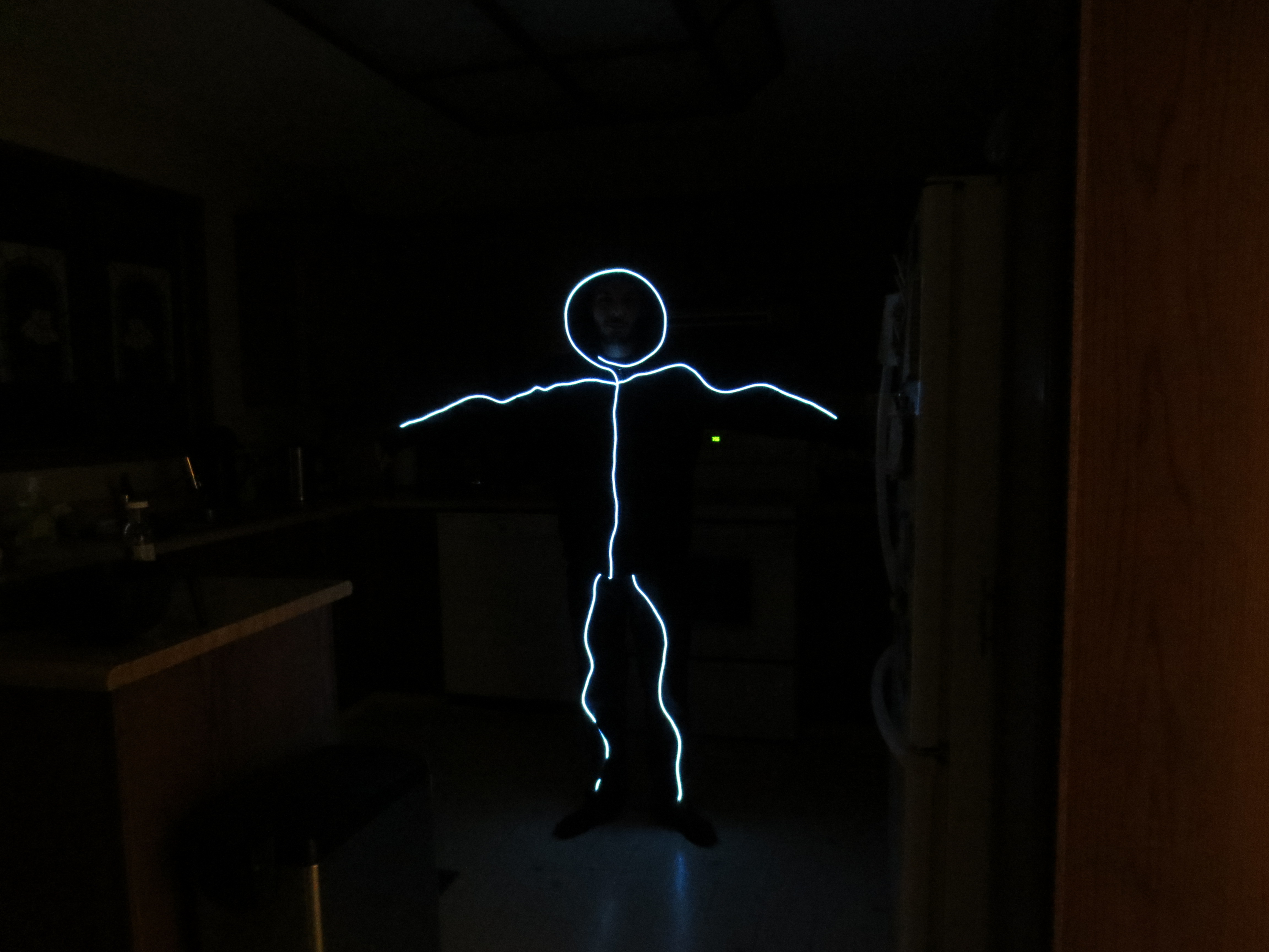
Like most people on the internet, I saw this video leading up to this year’s Halloween. Unlike most people, I thought “I need to make one of those, but adult male sized!” A quick bit of research led me to realize that normal LED light strips as used in the video are a little impractical for a suit my size. They cost more than 4x as much per unit length compared to High brightness EL Wire and they appear to consume far more power as well. Not wanting to carry piles of spare batteries around when I go out for Halloween, I decided to use EL wire and settle for the few tradeoffs it has. The most major tradeoff is that EL wire doesn’t hold up as well to repeated flex in the joints or tight bends. I may regret the choice to use EL wire if it fails on the dance floor, but for now it seems like the smarter choice.
. . . . .
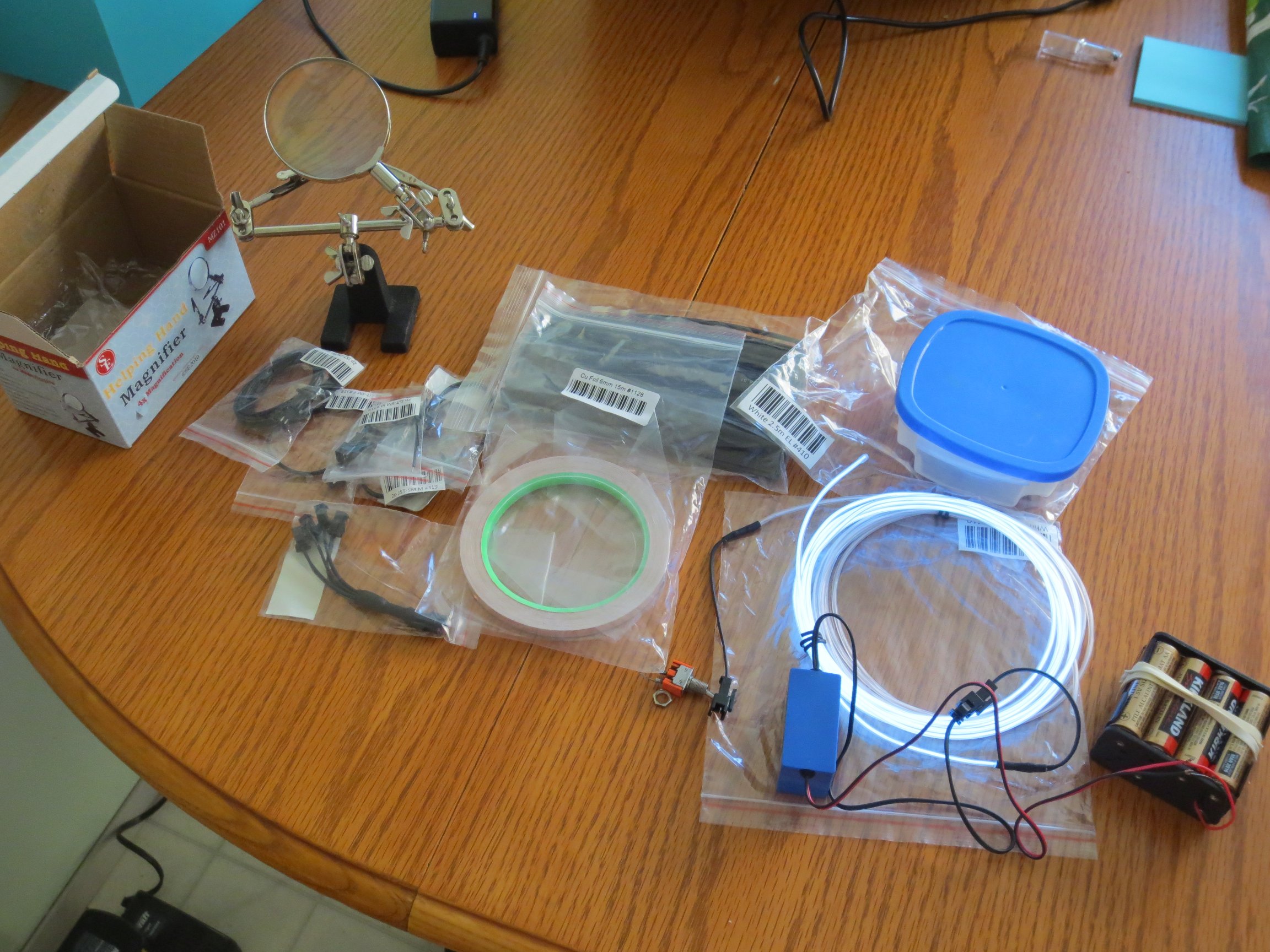
The Parts:
- 2 x 2.5m of High Brightness White Electroluminescent (EL) Wire
- 1 x 12V EL wire/tape inverter
- 1 x In-line wire 1-to-4 splitter
- 1 x In-line power cable 1 meter long extension cord
- 1 x In-line power wire connector (female)
- 3 x In-line power wire connector (male)
- 1 x Copper Foil Tape with Conductive Adhesive – 6mm x 15 meter roll
- 1 x Heat Shrink Pack
. . . . .
The Basic Design:
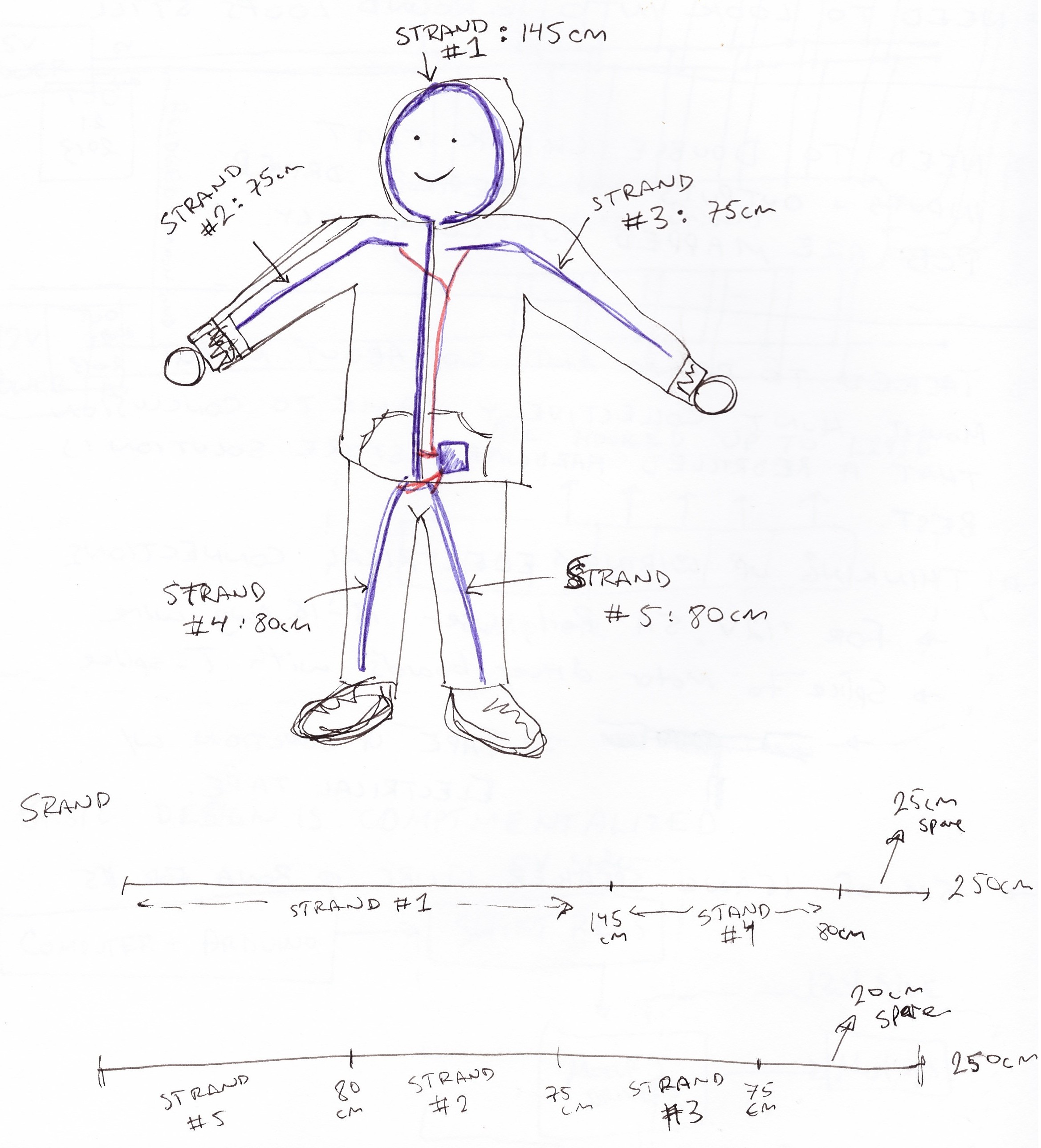
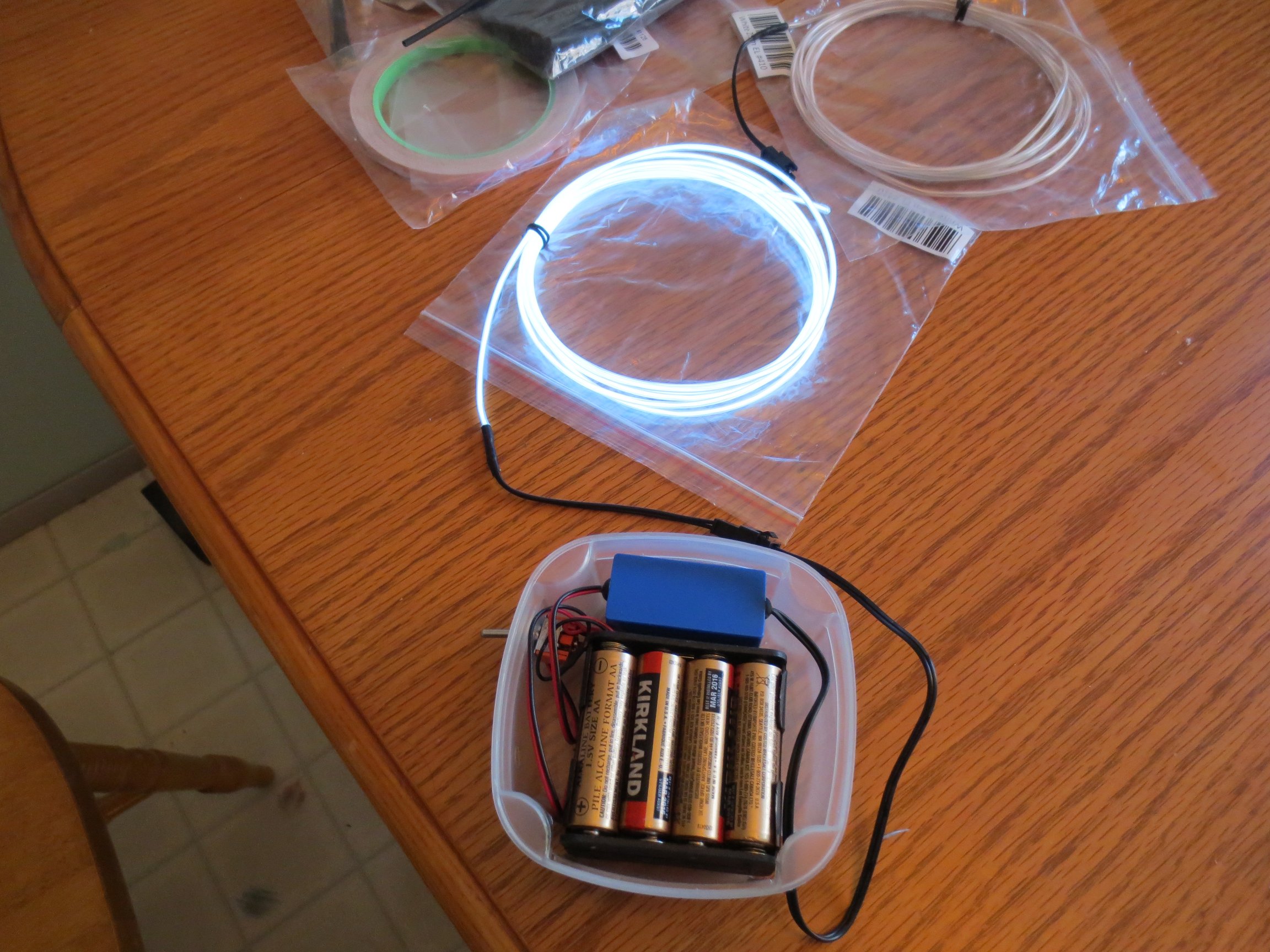
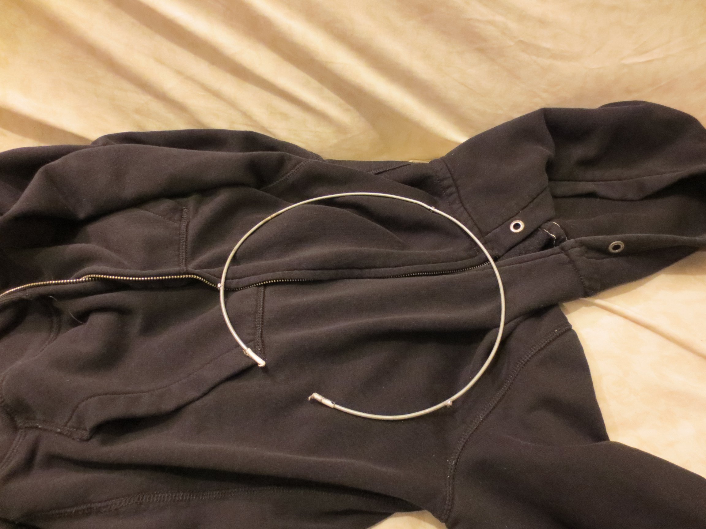
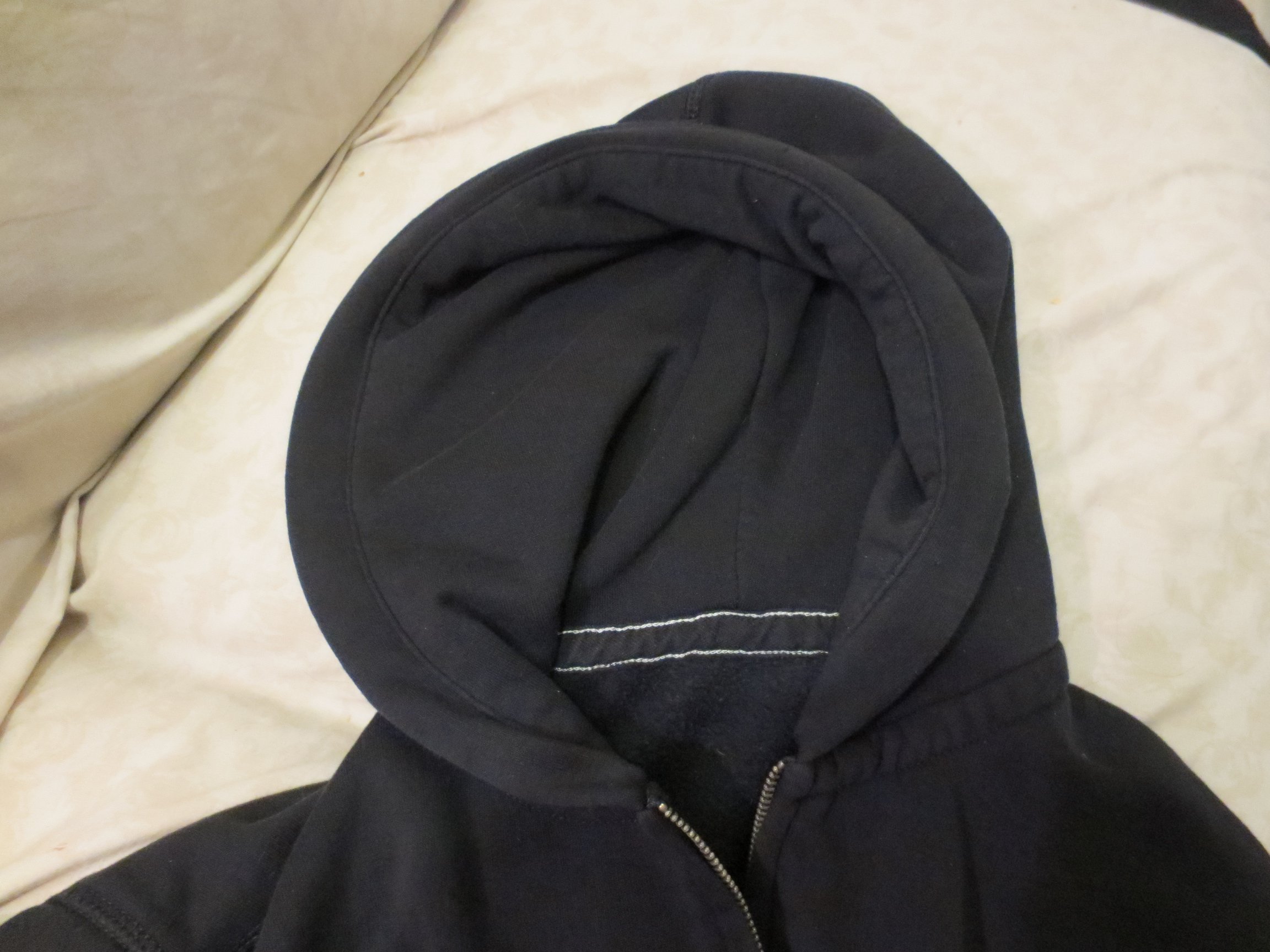
The suit consists of five separate strands of EL wire of varying lengths all connected to the inverter and power source. The hood of the suit is held into a circular shape using an aluminium ring that was salvaged from an old tomato cage. The inverter and battery pack is crammed into a small reusable container that has been cut up and modified to house the components.
. . . . .
Preparing the Electronics:
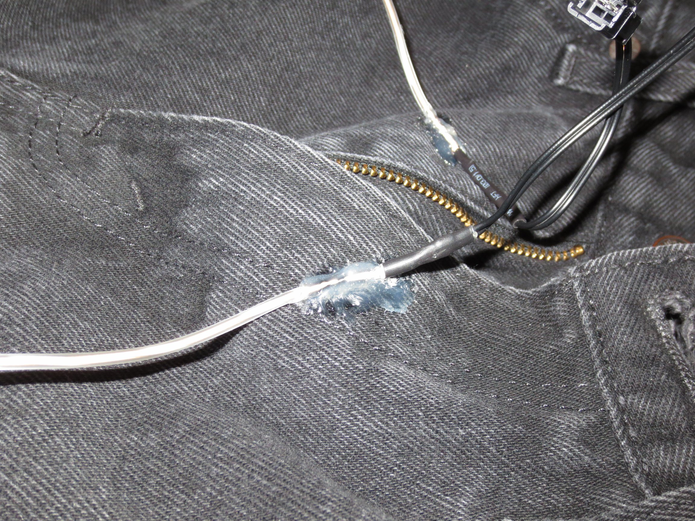
The strands of EL wire that I purchased both come with jumpers preinstalled, but since I needed five separate strands it was necessary to cut off the extra strands from the ends and manually solder new connections to them. There were three of these new strands to be soldered using the male in-line connectors. A few images of my soldering efforts are included, but the adafruit guide to soldering EL wire is far superior to anything I could reproduce here.
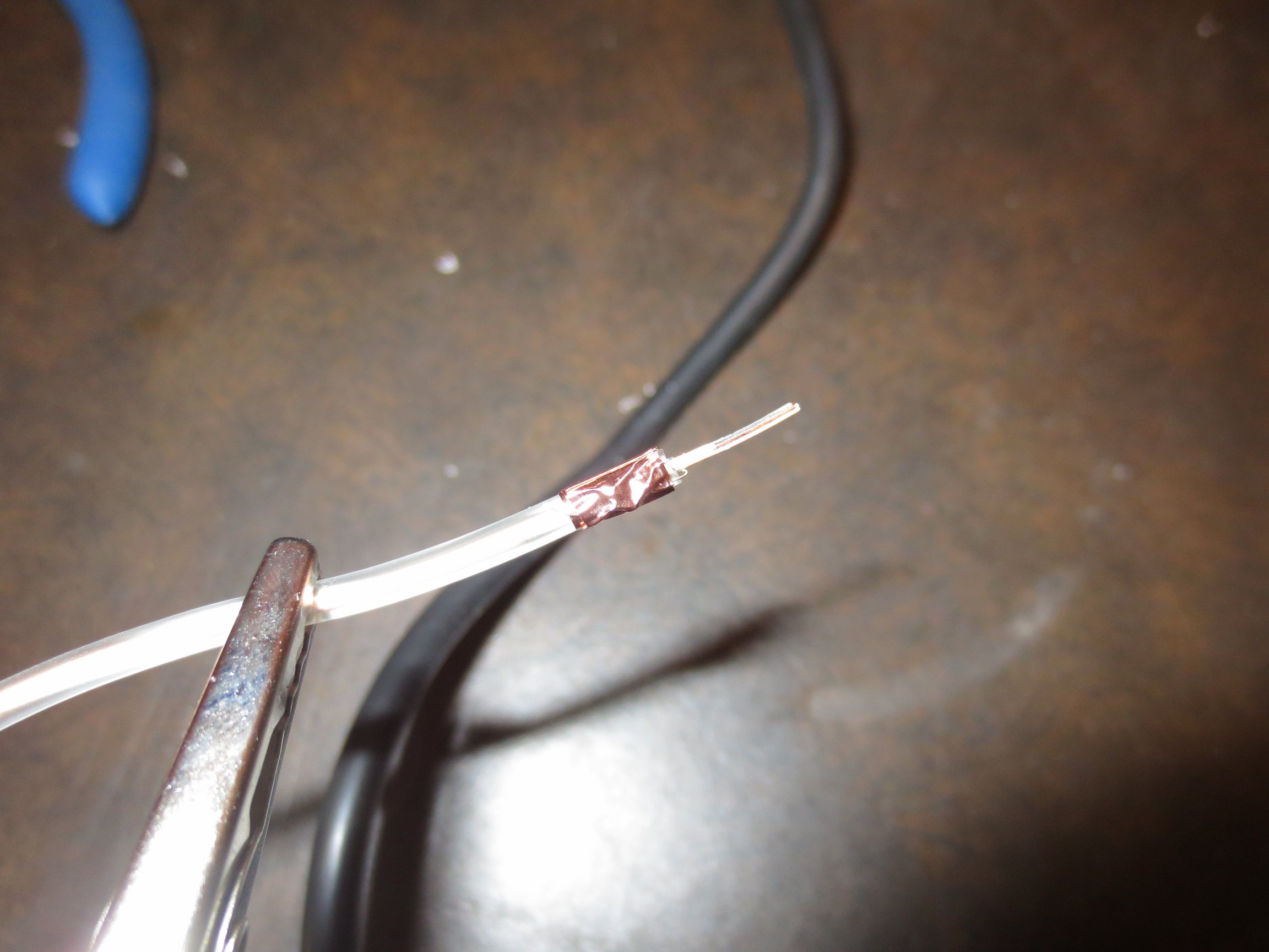
|
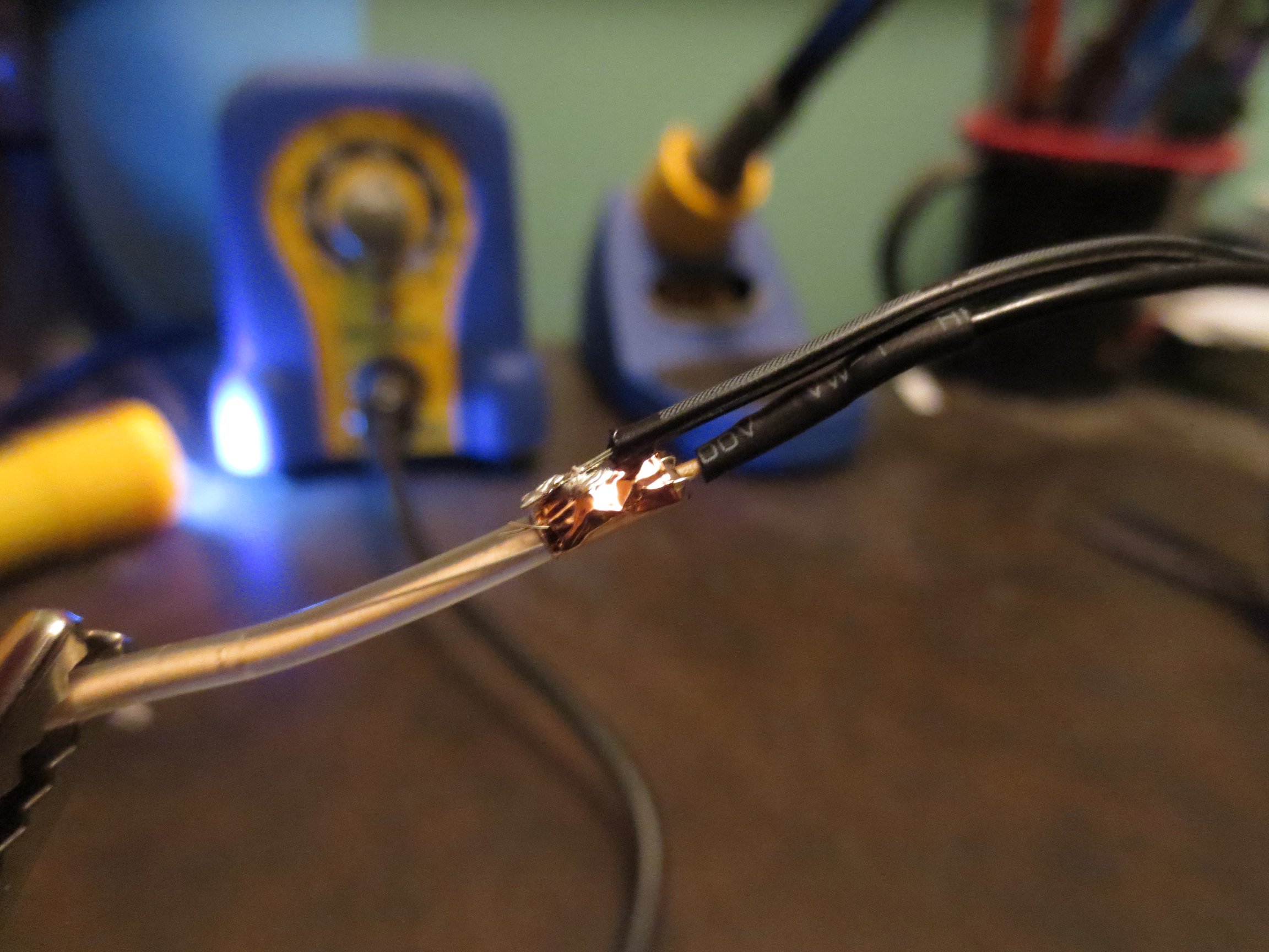
|
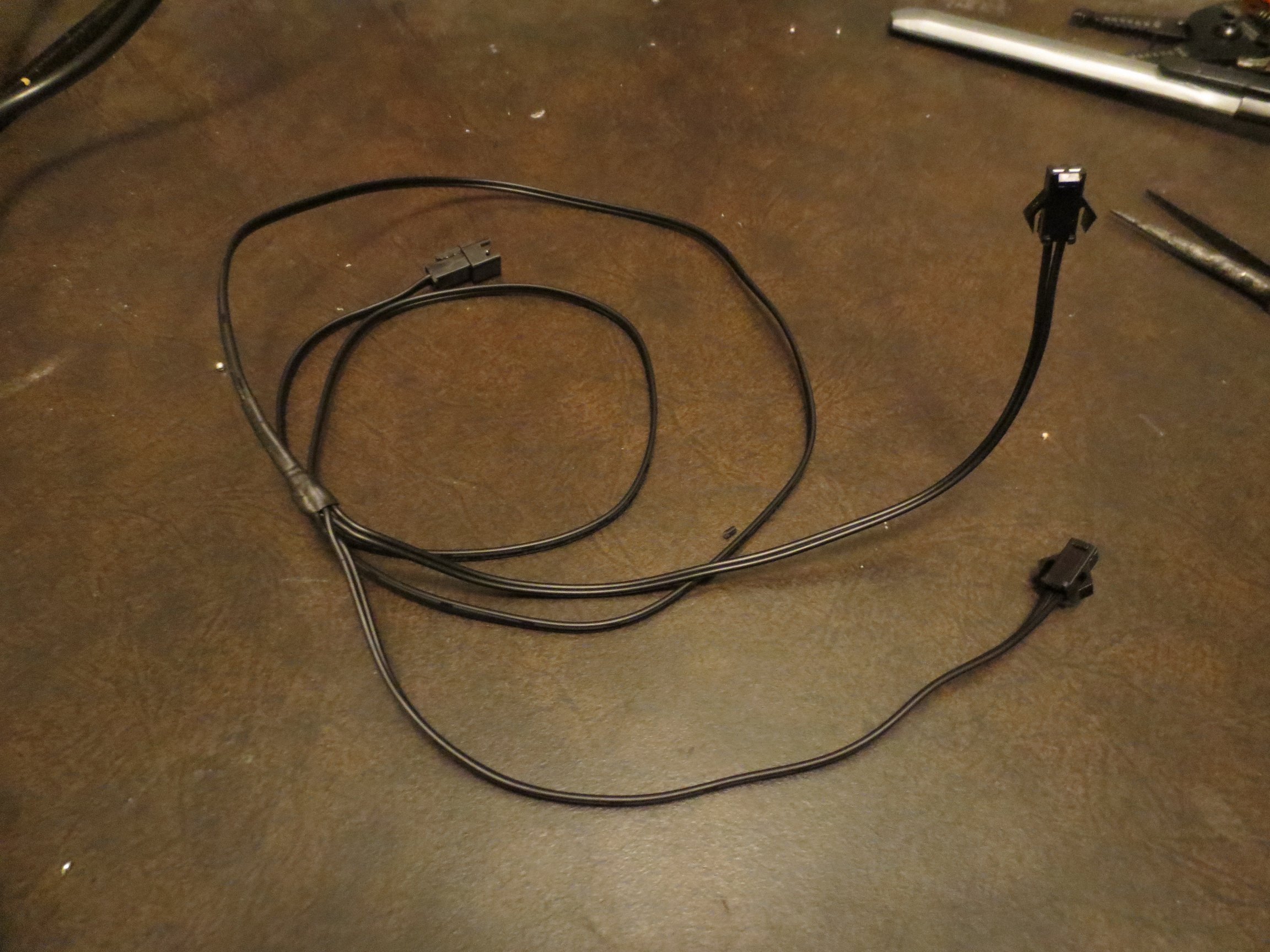
After cutting the EL wire to size and soldering on the jumpers it was time to prepare some of the other wiring essentials, like a Y shaped extension cable for the arms. This was done by simply cutting the female end of the in-line extension cord off, and then resoldering it with a the second female connector attached. The junction was then sealed up tight with a little heat shrink tubing that I slid on before I soldered everything.
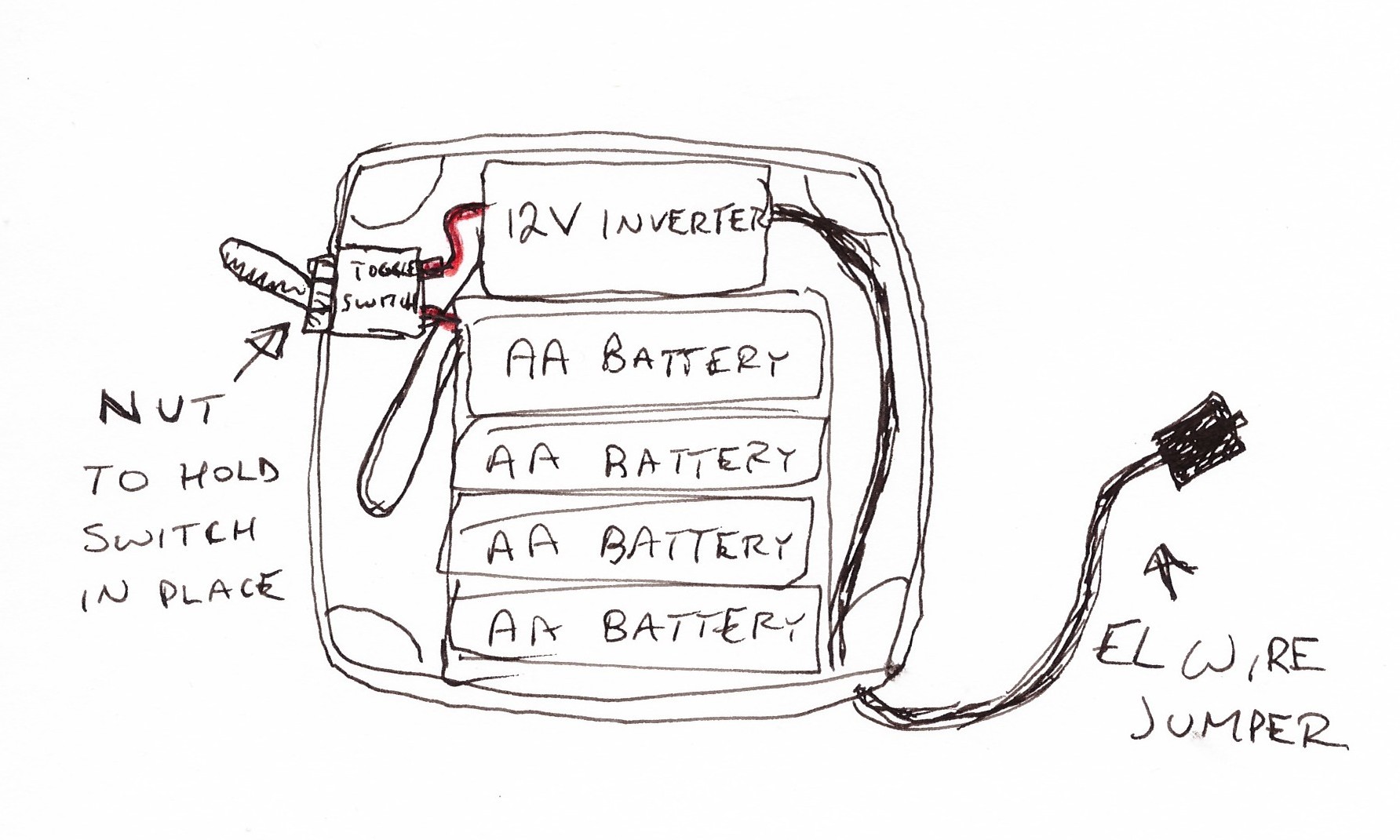
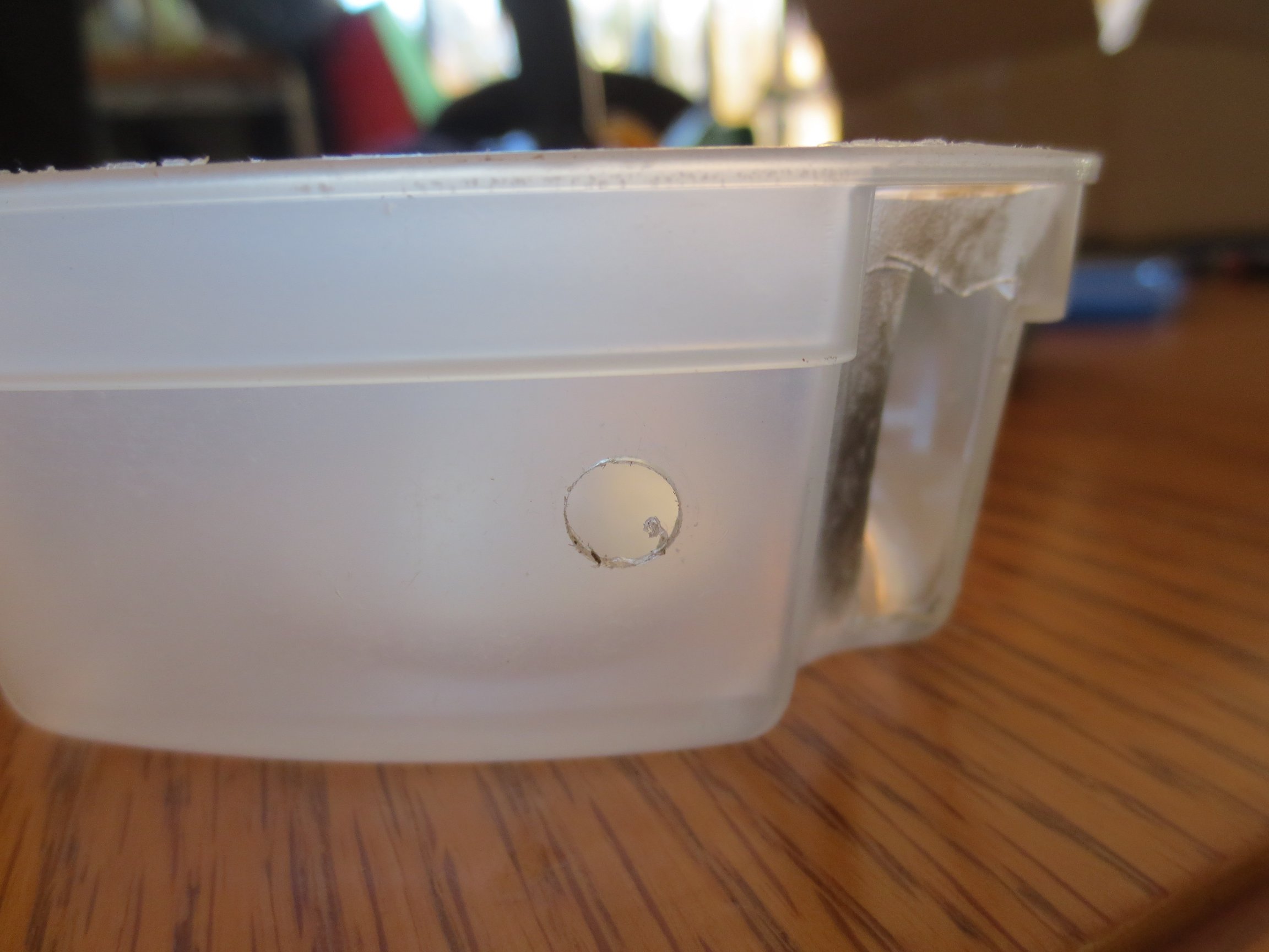
And finally, as far as the electronics are concerned, all that needs to be done is assemble the power supply and inverter box. The box, contrary to my measurements, unfortunately didn’t quite fit the battery pack and inverter. To fix this I decided to modify the box with a little lighter and X-acto knife surgery. After that, it was necessary to drill a hole for the toggle switch I planned to install. Technically I drilled the hole in the wrong place originally, and had to drill a second one. It’s not a mistake, just ventilation!
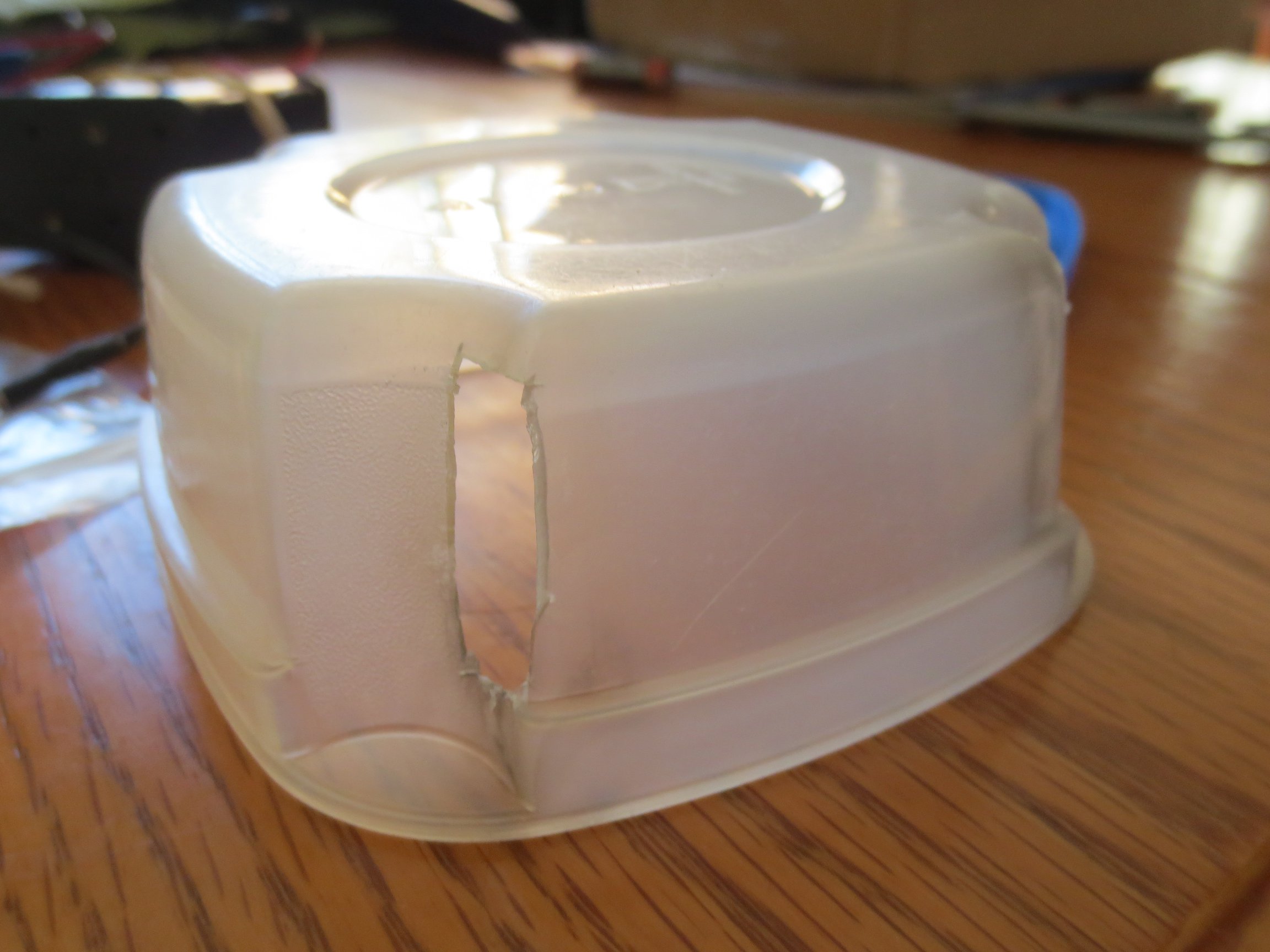
|
|
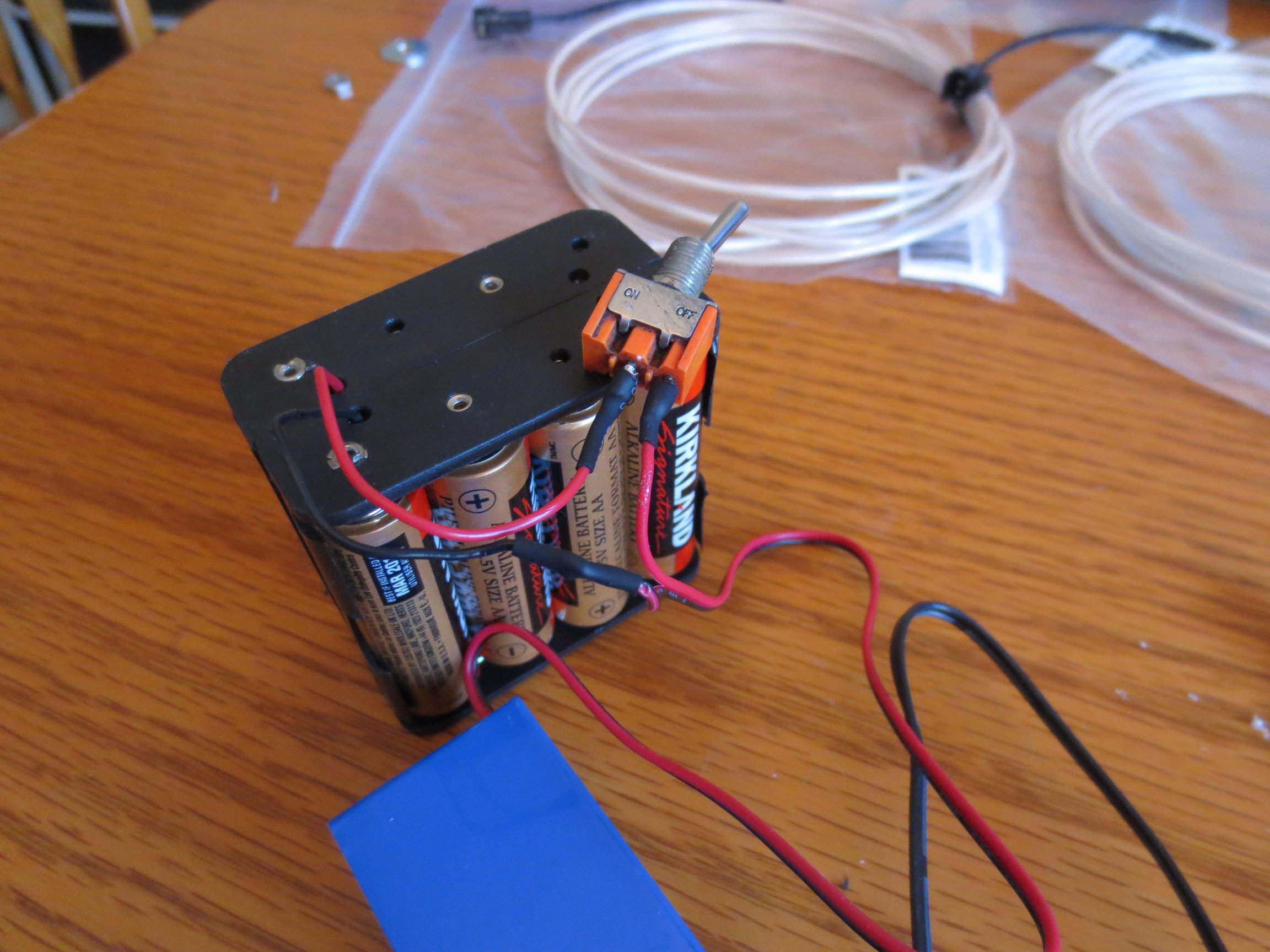
After getting the box ready to house the electronics, it was time to get soldering again. The connections are all really simple, I just soldered the two black leads together and then protected the joint with some more heat shrink tubing. After that the red leads were connected to the two terminals of the toggle switch I harvested from something too long ago to remember what it was. Once again, the connections were wrapped up tight with heat shrink tubing and then for good measure I placed a small bead of hot glue between them.
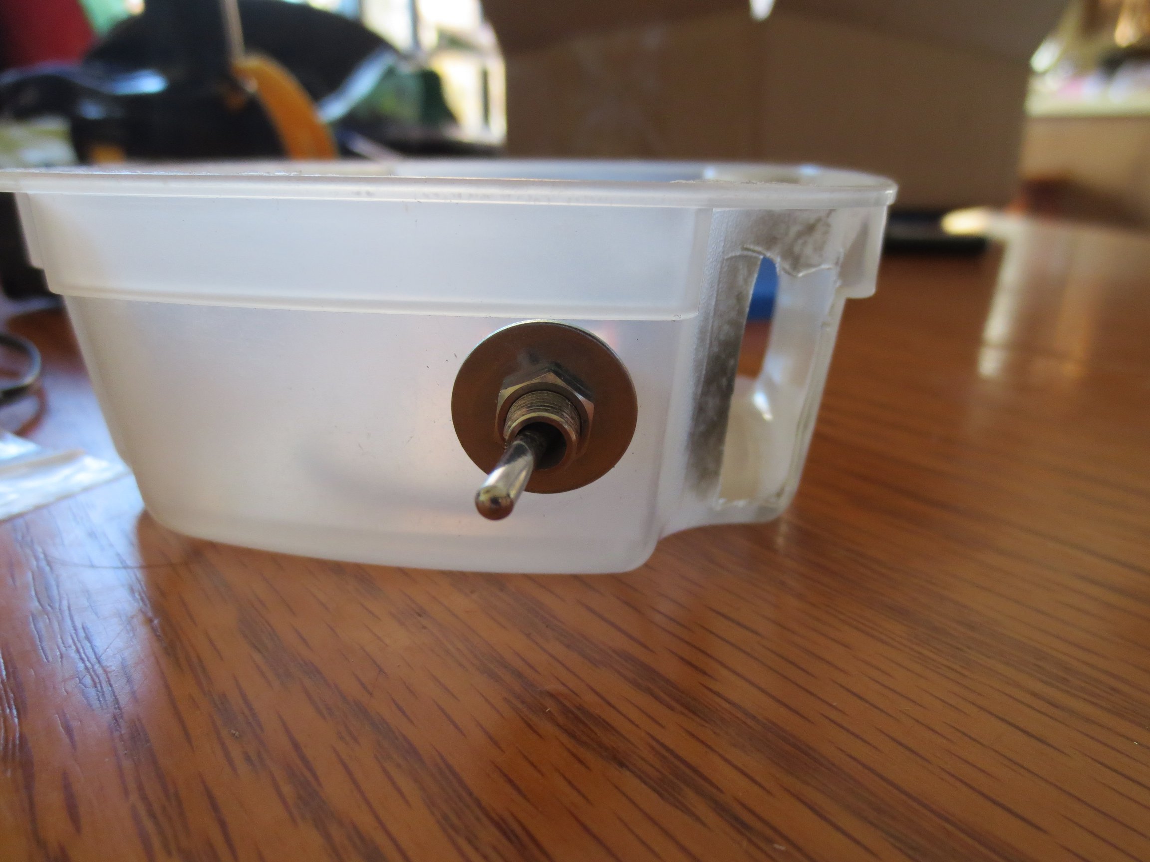
With the soldering done, I just had to fit it all into my box. This was really just as simple as screwing the nut onto the threaded bit of the toggle switch after sticking it through the hole that I had drilled, then squeezing the battery pack and inverter into there. Everything fits so snug that I didn’t need to do any fastening of the components to the inside of the box. Lucky me.
|
|
. . . . .
Attaching it to the Clothes:
Okay so the electronics are done, and everything glows nicely. Now we jut need to sew it to the clothing. But before that, I decided I wanted a nice round stick person head. To achieve this I went and pulled a nice firm aluminium ring from an old tomato cage then stuck it through the drawstring part of the hood.
|
|
To sew the EL wire on I used transparent thread, but that’s really just a fancy marketing gimmick used to sell 6 lb fishing line to the sewing demographic. I used a very simple rib stitch that wrapped around the EL wire then through the fabric over and over again. After this was done I decided to ensure the EL wire stayed put by further tacking it on using a few blobs of strategically placed hot glue. It’s okay, no one will notice in the dark.
I then started to sew on one of the arms, but due to my generally incompetent sewing skills, it failed to hold the EL wire in place after repeated movement. A little fed up, I resorted to the hot glue gun again. By putting little beads in places where the EL wire wasn’t moving too much and leaving high movement areas like the joints free I managed to get a solution that holds the EL wire onto the clothing well while still maintaining a good degree of freedom of movement. I repeated this process for the other arm and both legs, with the added benefit that it is much faster than sewing.
All that remained to be done at this point is to hook up the EL wire to the power box. This is where the 1 to 4 splitter comes in handy to connect to the torso/head, two legs, and the Y extension to the arms. All of this wiring is hidden inside the hoodie and threaded through a hole on the inside of the front pouch pocket where I’ve hidden the power box. That’s really all there is to it, and the costume is ready to go for Halloween.
