Vetinari's Clock: A Clock that Ticks Irregularly
I saw this sort of project posted on Hackaday a few months ago, originally using an Arduino, and quickly went to work building my own. It worked well when plugged into the USB port of my computer, and I was excited to hook it up to some batteries and see how long it would run (knowing full well that the Arduino was probably going to run them dry fairly quickly). It made it about 36 hours before the clip of 5 AA batteries was drained, and so I decided to try and rig it up with a 9V wall adapter power supply. Unfortunately, for reasons I am still unsure of, the whole thing would stop ticking after exactly 38 seconds and I quickly gave up in frustration. Luckily for me, Simon Inns came up with a version using a PIC microcontroller that runs much longer on only 2 AA batteries. Having never used PIC microcontrollers, I decided this was a good opportunity to learn something about them and used some money received at Christmas to order the parts and tools necessary for my own version of this clock.
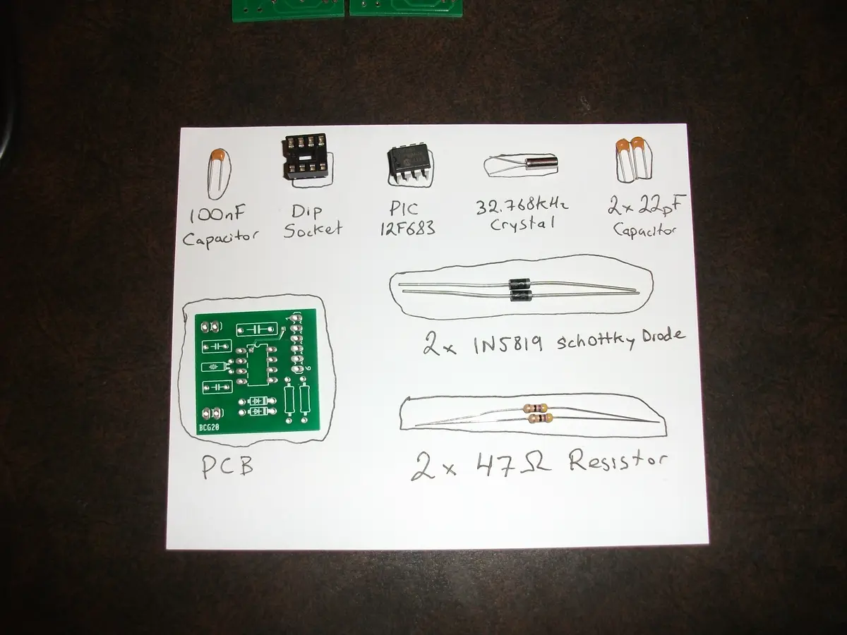
Each clock requires a PCB, a PIC 12F683 microcontroller, two Schottkey diodes (1N5819), two 47Ω resistors, two 22pF capacitors, one 100nF capacitor, a 32.768 kHz crystal, and a 6 pin 0.1″ header of some sort for programming (I used a male right angle header). It is also a good idea to use a DIP socket for the PIC microcontroller, so that it can easily be removed if necessary. Using the Cadsoft Eagle schematics and board files supplied by Simon Inns, I slightly rerouted one of the traces so that it would pass the DRC Bot (an automated program to check that prototype boards conform to the rules) at BatchPCB.com and ordered a couple of the boards. I was pleasantly surprised when they arrived and I found 4 boards, all of which appeared to be in perfect condition. Altogether, the materials necessary for a single clock cost less than $20 (not including the tools to program the PIC or the shipping fees).
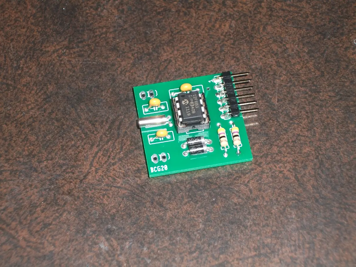
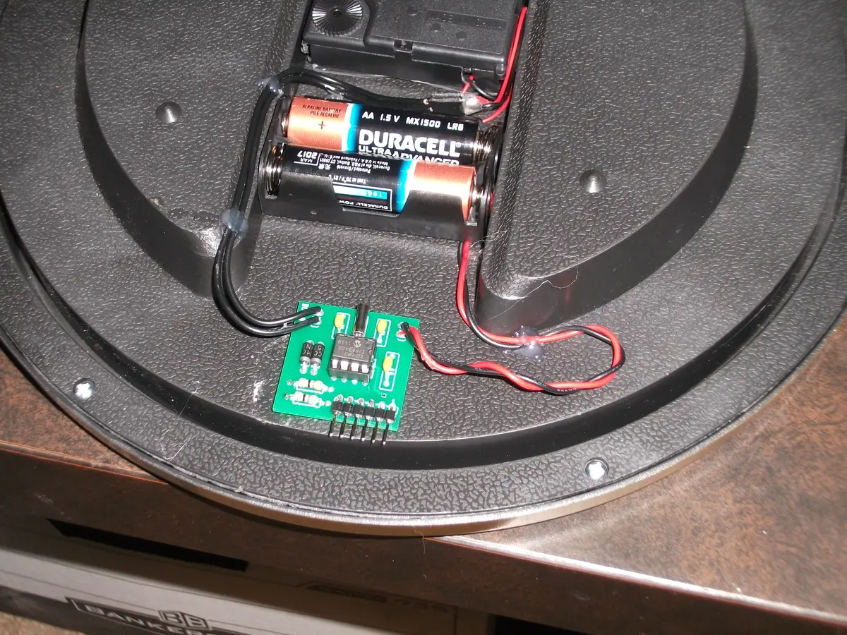
I started by soldering everything to the PCB which was straight forward, though the capacitors I purchased were different from the ones originally used by Simon Inns, and I had to bend the leads to make them fit. The picture to the right shows all of the components soldered into place, with the exception of the leads for the clock and battery clip. It is also important to make sure the Diodes are installed in the correct direction, or else they will not properly protect the microcontroller from the flyback voltage that is generated by the solenoid in the clock mechanism.
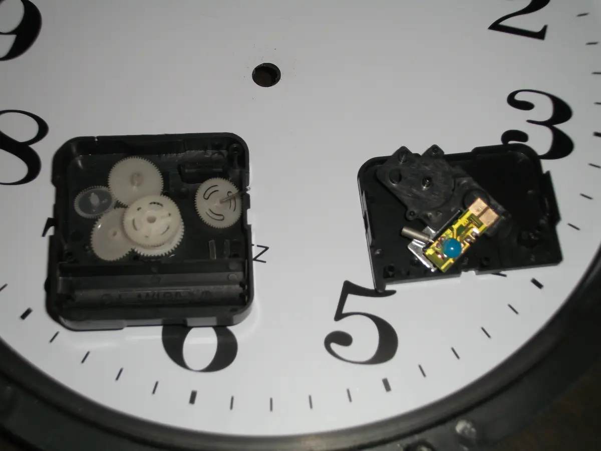
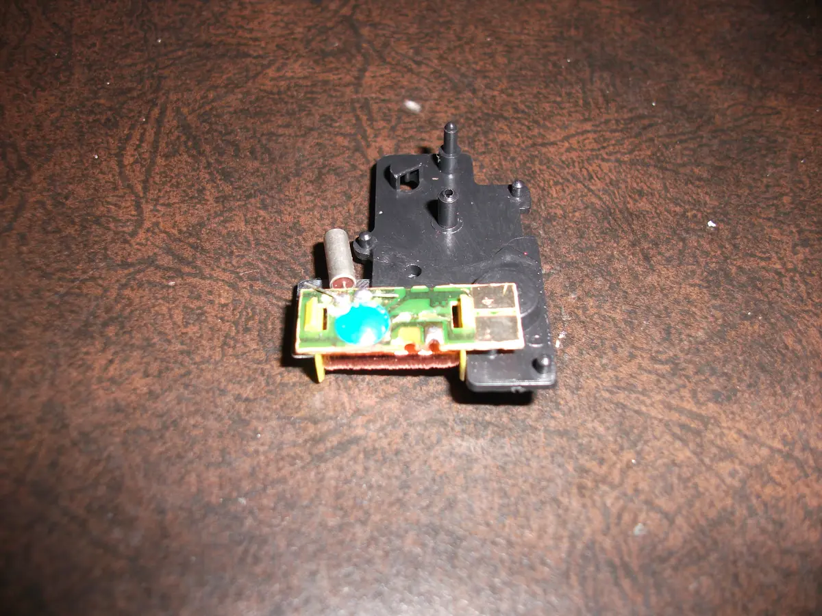
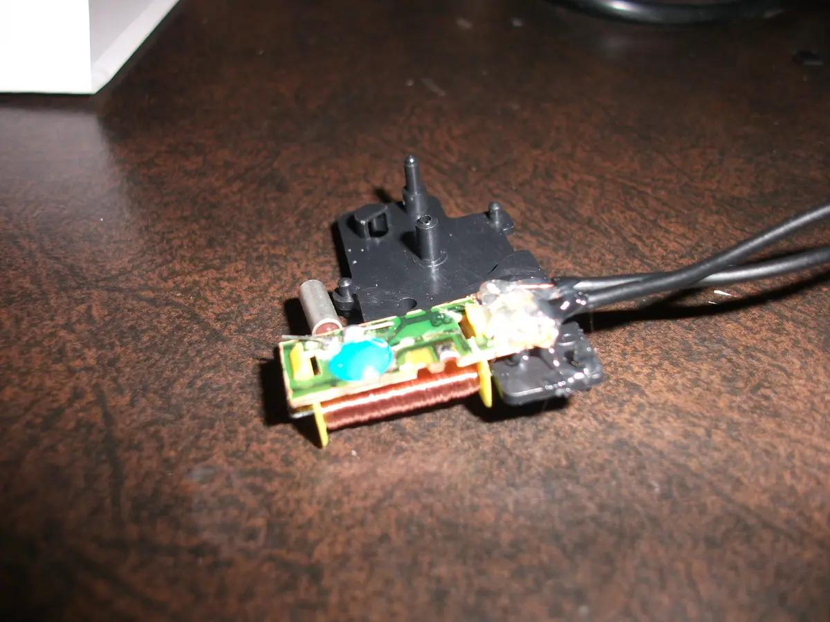
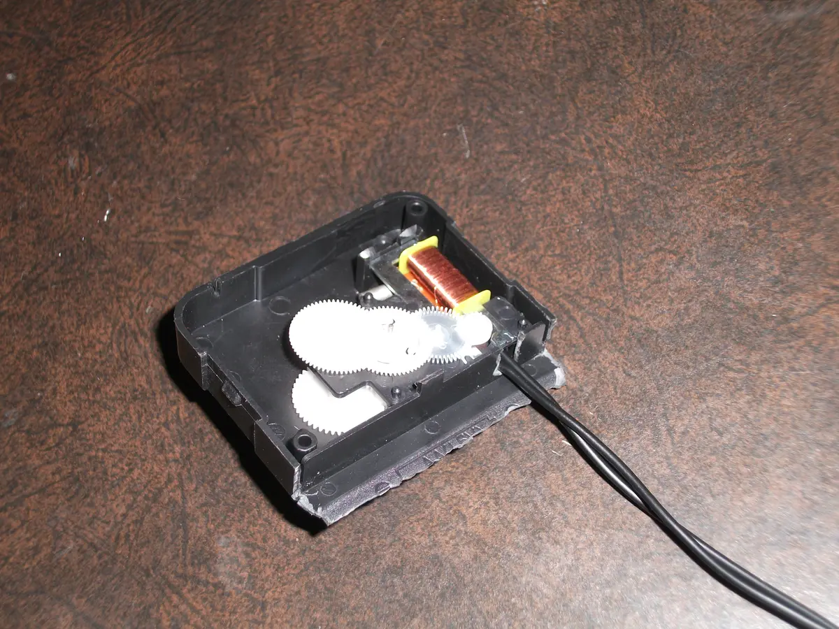
Next it is necessary to dissect the clock, and hook up the solenoid that drives it to our circuitry instead of the little board that normally drives it. In theory this is simply done by cutting the traces to the little pads near the bottom where the solenoid attaches, and then soldering our own wires to it, though the board inside the clock is cheap, and the copper pad itself delaminated from the board almost immediately upon trying this.
Not to be defeated, I simply rerouted the thin wires of the solenoid to the large copper pads that were formerly the contact points for the battery, and made all of my connections there. I followed that with plenty of hot glue to keep everything firmly in place, and then went about putting the clock mechanism back together. Unfortunately for me I neglected to double check that everything was functioning before I glued it, which caused some issues later. Lesson learned: check your solder joints BEFORE you smother them in glue.
In order to reassemble the clock, I had to cut a notch in the housing to make space for the leads I had just soldered on, and I also trimmed off most of the plastic that formed the original battery holder, since it was no longer necessary. After replacing the back plate and soldering the battery leads (make sure the polarity is correct!) and the clock leads in place on the PCB, I then hot glued everything to the back of the clock and stuck in a couple of batteries.
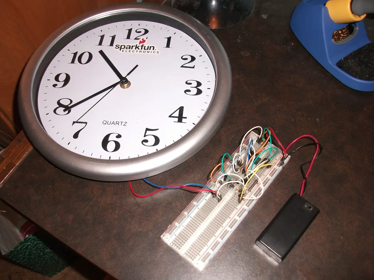
This was the point at which I realized something had gone wrong, since the clock was not ticking like the one I had already assembled using a breadboard. At first I was worried that one of the components on the PCB had been fried, but my trusty multimeter assured me otherwise when I saw pulses of voltage at the point where the clock leads had been soldered onto the PCB. This was were I realized that the problem must exist at the solder joints in the clock, which I had already hot glued. Oops! Luckily I already had a functioning clock mechanism from back when I assembled my power hungry Arduino version, which I had already hooked up to the breadboard version seen left. I cut the leads between the clock and the PCB, and swapped out the broken clock mechanism for the functioning one. Since both clocks were the same, this was a trivial task (thankfully).
Finally the clock was assembled and functioning, and I used some more hot glue to hold everything in place, including all of the wires. I also strategically positioned the PCB so the 6 pin programming headers would face downwards for easy access. Uploading the program the PIC is fairly easy, and I accomplished it without any issues by using the PICKit 3 with Microchip’s MPLAB X IDE. At the same time, I decided to re-brand the clock (no name dollar store brands don’t cut it) using some stickers I got when I ordered the components. I have had the clock running on a fresh pair of AA batteries since January 11th, 2012, and while it fell behind the clock on my computer by 10 seconds in the first two days, it has maintained accurate time since. My plan now is to leave it on my wall and test how long it runs on a pair of batteries and to compare that to the back of the envelope calculation I did earlier, which predicted at least 60 days for lower capacity batteries. While I have not yet noticed any brain mushification as a result of the clock, it seems like it disrupts my sleep slightly by causing me to wake more often during the night. We’ll see whether the batteries or my patience for poor sleep give out first.
While over simplified, the circuit is basically 2 47Ω resistors in series, for a total of 94Ω. It operates at 3V, so the current draw is 3V/94Ω = 0.0319A = 31.9mA. But the clock mechanism is only powered for 30ms for each tick, which on average occur once per second, so the average current draw is 31.9mA * 30ms/1000ms = 0.957mA. The PIC microcontroller draws 11μA at 32kHz, which is essentially negligible in such a rough calculation. Rounding the average current draw up to 1mA, and assuming a cheap set of AA batteries with 1500mAh capacity, the clock should theoretically run for 1500 hours, which works out to 62.5 days. For a better set of batteries with 2500mAh capacity, we get 2500 hours of operation, or about 104 days. In either case, two AA batteries every 2 to 3 months is far better than 5 AA batteries every 36 hours. EDIT: The clock managed to go for about 5 months on a pair of batteries before it became noticeably slow. It was 10 minutes behind the correct time when I finally replaced its batteries.
